Next Tri-City Amateur Radio Club meeting
7:00pm Monday, July 7, 2025
Confluent Makerspace
285 Williams Blvd
Richland, WA
Next Tri-City Amateur Radio Club meeting
7:00pm Monday, July 7, 2025
Confluent Makerspace
285 Williams Blvd
Richland, WA


A very thick polifin heat shrink tube locks each joint into place.

Although not called for in the assembly manual, on recommendation from Brian W7BJN, a glue bead is placed at each nesting tube junction to prevent them from sliding back in over time. Constant movement in the wind at the top of a tower can cause them to work in according to Brian. Made sense to this crew.

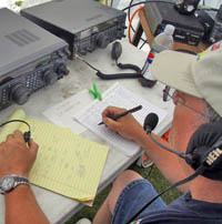
Dave W7DJE helps measure out an element tube. These nesting tubes are pulled out, and the ends are trimmed to length with a hacksaw.

OK, how to these hollow fiberglass tubes go together??

All the cabling prior to clean up.

Coax switching unit. All three active elements may be driven.

Installing the driven element return fixture.

Director element EHU and element return fixture.

Distance between this driven element EHU and the element return fixture is critical. Houston, we have a problem. The driven element is centered on the mast, which means it will loop around the tower. This will cause great difficulty with the tower guy lines.

Both the EHU and Element Return fixture must be leveled, then torqued to specifications.

The reflector EHU and element return fixture mounted on boom.

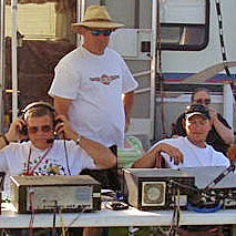
Steve WA7DUH; Peter's wife Tacy (on the end); Gary W7TYQ and Dave W7DJE trying to program a 2M handi-talkie; and Peter AC7SB.

Many parts to each unit..

Assembling an element housing unit (EHU) prior to installation.

The interior of a SteppIR Element Housing Unit (EHU) with stepper motor that drives copper-beryllium tapes in and out of the hollow antenna element tubes. The tapes are the radiating/active elements of the Yagi beam antenna. This SteppIR antenna is able to be resonant anywhere between 6.5 Mhz and 54 Mhz by adjusting the lengths of the Beryllium tapes. The tapes are wound on the spools that are seen in the picture using the cogged wheel that engage holes punched into the tapes. Cogged wheel is driven by a stepper motor, which has absolute positioning capability. The computerized controller knows how far to position out the tapes in the driver, reflector and director tubes for any given frequency.

Gary (W7TYQ) Dave (W7DJE) and Peter (AC7SB) attach the reflector Return Element Support to the boom.

Peter Rosenberg (AC7SB) from Fall City WA joins the antenna assembly team. Steve (WA7DUH), Peter and Gary (W7TYQ) apply anti-sieze compound to the staddles that will be used for one of the Return Element fixtures. Liberal use of anti-sieze compound is critical because of the many dissimilar metals used in both the antenna and hazer (aluminum, stainless steel hardware and galvanized steel.)


