

Yes, the droop is normal. Note the middle driven element has not been installed in this picture. The tree has to be removed.

A completed element. 30M & 40M beam operation is achieved by pushing the beryllium tape through the sweep and down the "return" side, creating a resonant folded element. Thus these elements are only 40 feet wide instead of the 62 feet that would be required if they where straight out.

Rubber boots hold the elements into the EHU sockets.

Assembling an inner guide and support tube that is slid into the large end of the element tubes to provide a consistent diameter for the beryllium tape that must slide in and out.

After assembling 1 of the active elements on the grass by the tower in about 3 hours, assembly was moved into Steve & Linda's shop where an assembly line could be set up, as there are 6 of these to make. Time was reduced to about 1 hour per unit.

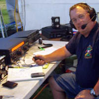
There is a lot of electronics and relays that go into this antenna. Pictured is Gary W7TYQ that came up to help from Yreka CA.

Control lines from each active element and the coax switching relays come together into junction terminals.

A very thick polifin heat shrink tube locks each joint into place.

Although not called for in the assembly manual, on recommendation from Brian W7BJN, a glue bead is placed at each nesting tube junction to prevent them from sliding back in over time. Constant movement in the wind at the top of a tower can cause them to work in according to Brian. Made sense to this crew.

Dave W7DJE helps measure out an element tube. These nesting tubes are pulled out, and the ends are trimmed to length with a hacksaw.

OK, how to these hollow fiberglass tubes go together??

All the cabling prior to clean up.

Coax switching unit. All three active elements may be driven.

Installing the driven element return fixture.

Director element EHU and element return fixture.

Distance between this driven element EHU and the element return fixture is critical. Houston, we have a problem. The driven element is centered on the mast, which means it will loop around the tower. This will cause great difficulty with the tower guy lines.

Both the EHU and Element Return fixture must be leveled, then torqued to specifications.

The reflector EHU and element return fixture mounted on boom.


